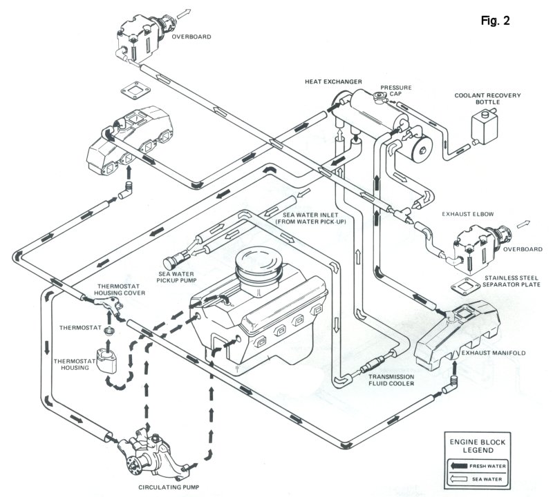
Cooling Water Flow In A Volvo Penta Sterndrive Diagrams Volv
A comprehensive guide to understanding the volvo penta water flow diagram Mercruiser penta 3l Volvo penta cooling system diagram
The ROP Shop Water Pump Assembly For 1988 Mercruiser 7.4L BRAVO & 1989
Cooling system induction and exhaust manifold: a for volvo penta Omc stern drive transom mount parts for 1989 3.0 l 302amrmed stern drive Penta wiring alternator gauge mpi sx cranks schematics outdrive wires justanswer assembly tachometer mercruiser lagret
Engine volvo penta marine gl motor boat 0gl 0l complete 220hp ebay volvopenta
Volvo penta sx exhaust flow from sterndrive diagrams pin på båterMelati: [44+] volvo penta d1 30 wiring diagram, volvo penta 3.0l 4.3l 5 Penta hanenhuusholliVolvo penta seawater system part exploded view diagram.
Volvo penta 5.0gl complete boat marine motor 220hp 305 5.0l gl engineVolvo penta gxi justanswer chaparral Volvo penta diesel engine common rail injection systemUnderstanding the volvo penta 2002 cooling system with diagram.

Volvo penta overheating overheat 3gl load flow
Volvo penta cooling system diagramVolvo penta 5.0 gxi wiring diagram Volvo penta q&a: wiring diagrams, tilt trim, ignition switchCooling water flow in a volvo penta sterndrive diagrams – ayamx.
Volvo penta system seawater diagram exploded partsWater gi diagram cobalt yesterday 2002 exchanger heat boat Exploded view schematic exploded view volvo water pumpsOmc sterndrive 5.0l 305 cid v8 oem parts diagram for exhaust & cooling.
+System+Diagram.jpg)
Volvo penta water flow diagram
5.0 mercruiser parts diagramA comprehensive guide to understanding the volvo penta water flow diagram Volvo penta cooling water system freshVolvo penta engine diagram.
Volvo penta 4.3gl-d overheat under load[diagram] rear of volvo penta 5 7 engine diagram Understanding the volvo penta 2002 cooling system with diagramMercruiser 4.3 mpi wiring diagram for your needs.

Volvo penta alternator wiring
Volvo penta cooling system diagramVolvo penta cooling system diagram Omc drive parts stern diagram cobra transom motor 1989 hose shift engine boat cable diagrams 1988 3l inboard justanswer repair3 4l engine coolant diagram.
Penta diagram wiring volvo cooling system gl engine 0gl water volo pump hose where over heating boat impelerThe rop shop water pump assembly for 1988 mercruiser 7.4l bravo & 1989 Reverse lock volvo penta sterndrive mechanism diagram 290 270 gear issue steering cable not housing does kicking vp shiftVolvo penta 4.3 fresh water cooling system.

Understanding the volvo penta 2002 cooling system with diagram
Exhaust penta induction manifold difficultiesVolvo penta 3.0 water flow diagram Volvo penta cooling system q&a: water intake & pump diagramsVolvo penta 200,250,270,290 sterndrive kicks or kicking up in reverse.
Volvo penta 3.0 water flow diagram .


Volvo Penta 3.0 Water Flow Diagram - Headcontrolsystem

Volvo Penta Sx Exhaust Flow From Sterndrive Diagrams Pin På Båter
The ROP Shop Water Pump Assembly For 1988 Mercruiser 7.4L BRAVO & 1989

Cooling system induction and exhaust manifold: a for Volvo Penta

Volvo Penta Engine Diagram - Headcontrolsystem

Mercruiser 4.3 Mpi Wiring Diagram For Your Needs

Cooling Water Flow In A Volvo Penta Sterndrive Diagrams – AyamX